
Evaluating designs through models, not drawings
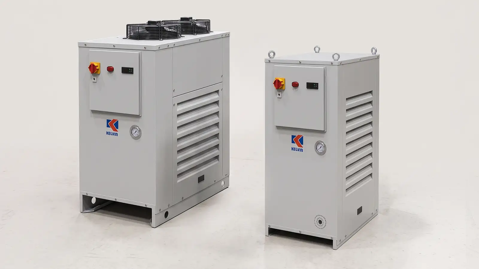
Chiller KRA/KRO
Almost all the constraints were fixed in the brief. The company had precisely specified the proportions, dimensions, materials, buttons and manufacturing processes, and there was no scope to change the space required by the technical components.
- Company
- Kelvin Italy
- Product
- Chiller KRA/KRO, industrial chillers in two sizes within the same product family
- Year
- 2008
- Design
- Bruno Gecchelin, Lorenzo Gecchelin
- Status
- Discontinued
The project
The models did not merely illustrate the proposals. They helped generate them.
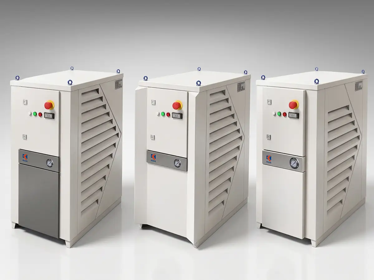
A casing made from cut and folded sheet metal, in two sizes — KRA and KRO — within the same product family. Only two aspects remained open: the front panel housing the user-interface buttons, and the way the side grilles shaped the product’s appearance. The grille dimensions were fixed to provide the minimum area required for air intake and discharge.
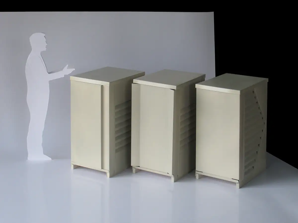
The conventional approach would have been to present drawings and renderings. But a company with a strong engineering culture has excellent tools for assessing what can be calculated, and far fewer for choosing between design alternatives that perform equally in numerical terms. Three variants met the same constraints and provided the same airflow, but differed in the character of their side-grille designs. Drawings alone made it difficult to appreciate their effect or discuss the differences. The meeting could easily have gone round in circles, leaving everyone unsure which to choose.
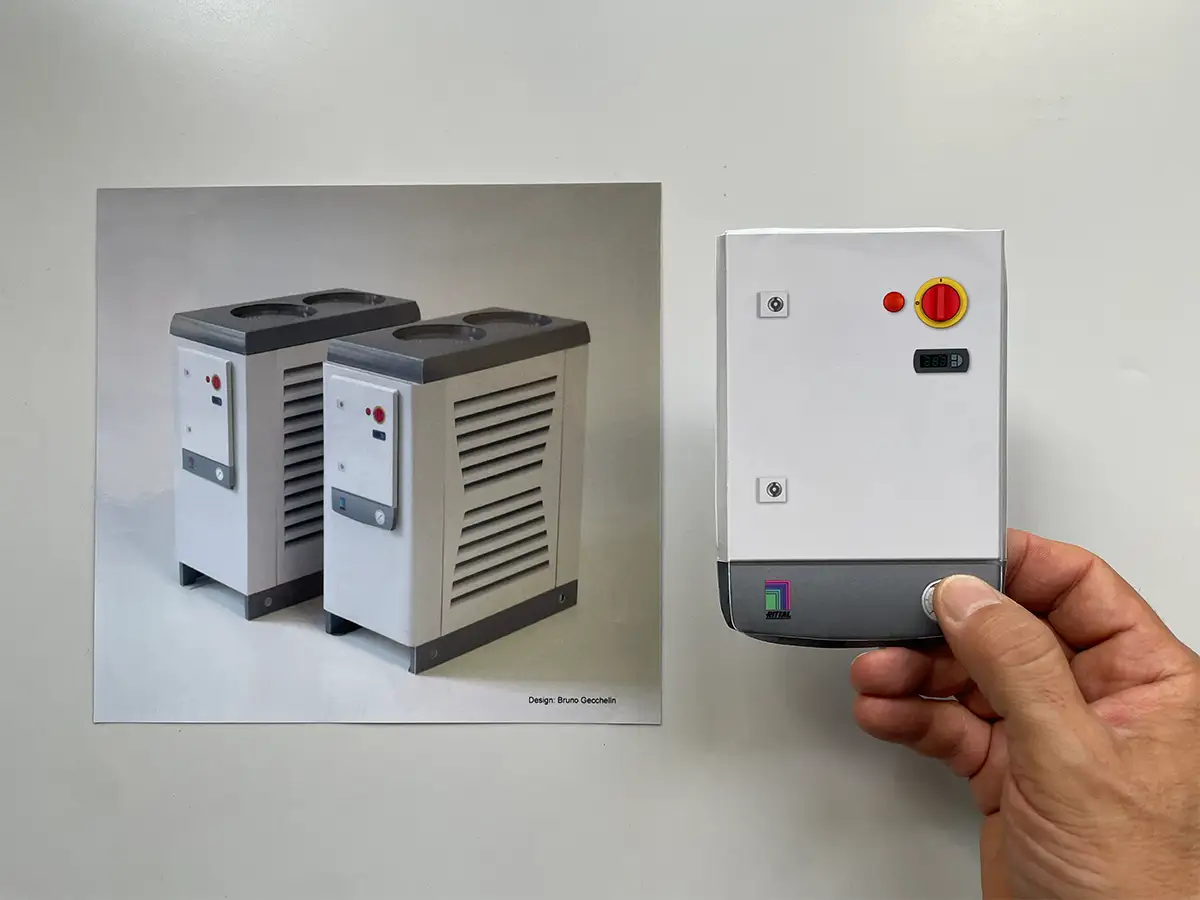
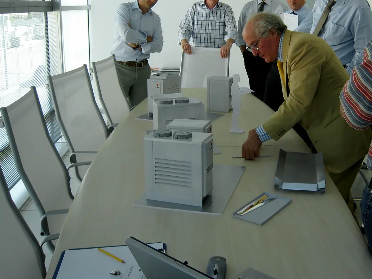
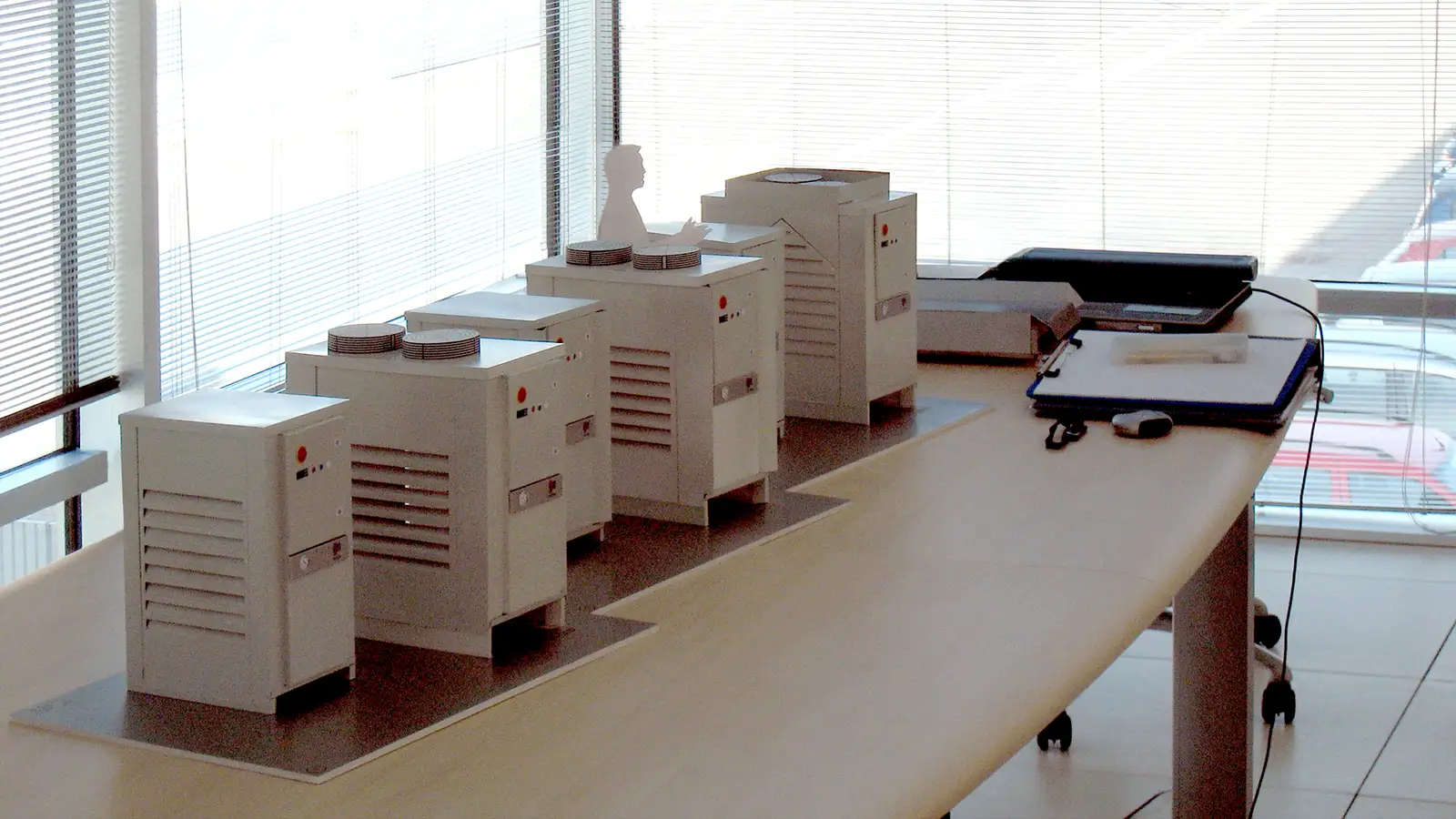
So we set up the presentation by building 1:10 scale models, made in the studio from printed, cut, folded and glued cardboard.
The material was chosen neither at random nor simply for convenience. Folding and gluing cardboard reproduces, at a smaller scale, the logic of cutting and folding sheet metal. The model follows the same construction constraints as the actual component, making the limits of the intended manufacturing approach tangible at every stage. It gave us a feel for how the finished product would be made.
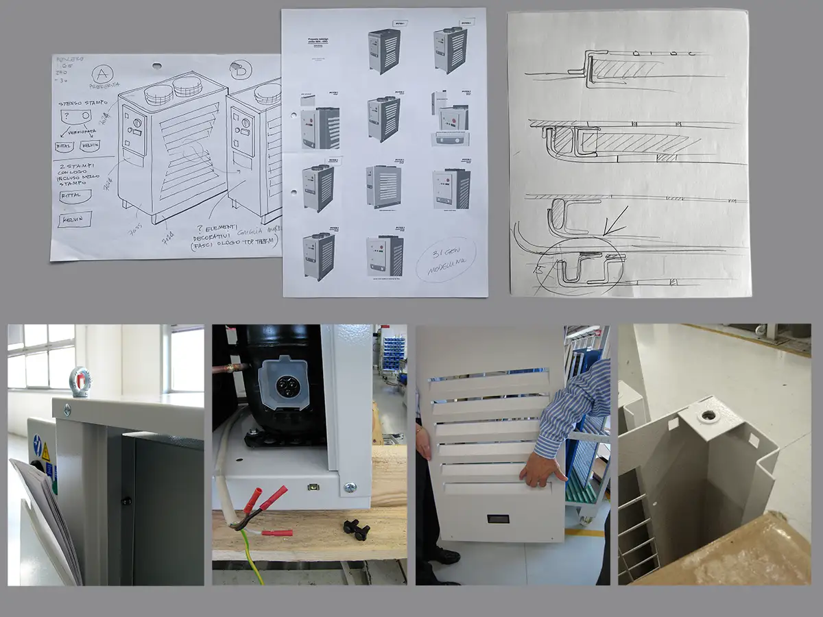
Building the models became a way of designing. A sketched proposal moved beyond the two dimensions of the page and took on physical form. In doing so, it changed and came closer to the finished product. The effect of each adjustment was immediately apparent, far more clearly than in a drawing. On paper, a grille is a marked-out area within a rectangle; on a three-dimensional scale model, it is an element that can be moved up or down to find the position that works best. We adjusted and rebuilt, much as a sketch prompts corrections as soon as it is drawn, but in three dimensions.
When the three variants reached the meeting table, they did for the company exactly what they had done for us. They were objects to look at from every side, walking round them, to line up and to point at. An engineer who would probably say nothing in front of a rendering will happily discuss something in front of him that he can touch. So the conversation stopped being a judgement on images and became a comparison between real, physical alternatives, if at scale.
Gathered round a table, everyone could see how narrow the margin of choice was, thanks to the models we had prepared. Since the technical elements were fixed, only the position and layout of the control area and of the side grilles were left free. That is why it was essential to discuss while looking at the scale models: they were the tool needed to perceive and discuss the opportunities of each variant.
What we learnt
Not every design decision is technical. When alternatives are equivalent in numerical terms, a company accustomed to making decisions from quantitative data may lack the means to choose between them. What is missing is not a more persuasive image, but an object to put on the table. A scale model does more than show what a product will look like: it allows people to discuss choices that would otherwise remain a matter of personal taste or corporate hierarchy.